
1. Introduction to the Matte Paint process. Part II
Summary – in this part of the tutorial we will learn how to create a basic projection and then how to expand it to a standardized layout for matte paint. At the end of this chapter you will have a general understanding over the whole process related with the matte paint creation.
a. Building a basic projection rig in Nuke:
We need to create the following nodes for building a camera projection setup:
note: press Tab key in the Node graph area, in Nuke and write the bold (blue) names from below: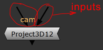
input – the little lines that are above some of the nodes in Nuke.
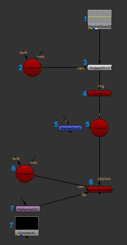
1.CheckerBoard node – our 2D node as a placeholder.
2.Camera node – this camera will be used for projection.
3.Project 3D node – will project the CheckerBoard node over the geo.
-cam Input – connect with the Camera node from point 2.
-unnamed input – connect with the CheckerBoard node
from point 1.
4.Card node – the geometry to project on.
-img input – connect with the Project3D node from point 3.
5.Optionally – Scene or MergeGeo node – these nodes can connect multiple pieces of geometry. Connect the input with the Card node created above.
Note:You can connect as many peaces of geo as you want to this two nodes. Pick the little arrows from the left side of this node for that.
6.Camera node – create another camera node for rendering the projection.
7. Optionally – Reformat or Constant node – this will give the resolution of you render.
-cam input – connect with the Camera node from point 6.
-obj/scn input – connect with the Scene or MergeGeo node from point 5.
Note: if you did not create the Scene or Merge Geo node, plug this input straight in the Card node from point 4.
-bg input – connect with reformat or constant node from point 7, if you create those.
Note: Your projection setup should look like in the image above.
At this stage, you may not see anything when you view your setup from the Scanline Render node. This is normal; we’ll fix it in a bit. Before we move forward with extra information about each node created, I would like to make a recap over how you should understand the setup of a 3D scene in Nuke.Nuke is mostly a 2D software but the 3D part works like a primitive version of a 3D package. Having intermediate knowledge in a 3D software, will help you understand the concept behind a 2.5D projection set up in Nuke.
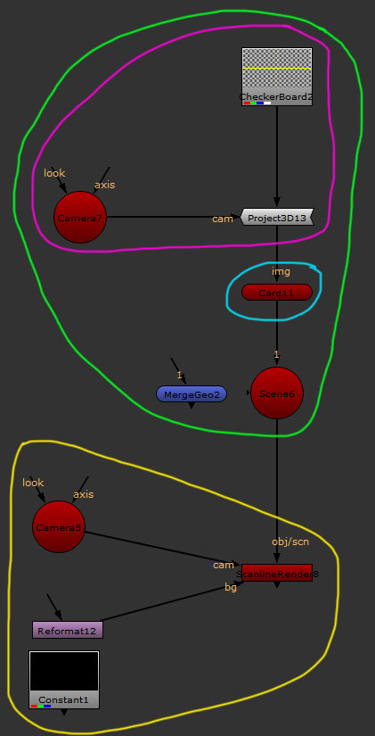
Pink – think about these nodes together like the process of mapping a texture on a geo with unwrapped UVs in a 3D software (like Maya, 3Ds Max, etc).
For loading a 2D image you will need to create a Read node. Feel free to explore the other options for 2D notes from the image tab.Note: This process, of camera projection technique, used to be the only solution for painting texture on geometry in the early stages of the 3D packages development.
Blue – this is where our 3D geometry will be brought in; feel free to explore the options for geometry under the 3D tab in Nuke.![]()
You can also import your custom geo, by creating a readGeo node and loading any abc, fbx or obj file format.
Green – all these nodes together should be understood like a collection of elements that we build in regular 3D packages.
ex: we build a piece of geometry, then we create UVs and then we apply the texture, based on the UVs. All elements created are held in a scene –this is the role of the Scene node or MergeGeo node.
We build our 3D model and now it’s time to render it. This requires the following nodes:
Yellow – at the end we use the render setup (ScanlineRender) to tweak the render quality. We also need a render Camera from which we render and we also need to define the render resolution (Reformat).
Once the projection setup is understood we will move forward in making it work. At this point, all the 3D elements that we created are placed in the center of the 3D scene. Both Cameras, together with the Card geo are overlapping, this is the reason why we can’t see anything when visualizing from the render node.
While you have the mouse cursor over the viewer area, press Tab. This will switch to 3D scene.
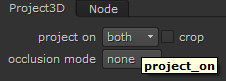 1. Select Project3D node then go to settings. Under project on option, switch to both from front. This will project the image on both sides of the card.
2. Select the card, a XYZ axes will be visible; by holding CTRL+SHIFT plus LMB scale up the size of the card.
3. Select the Camera for projection and move it back so you can see the checker board projected on the card.
4. Select the camera for render and push it back so you can have both projection camera and the card in the visibility cone.
In the end you should have a scene that looks like this:
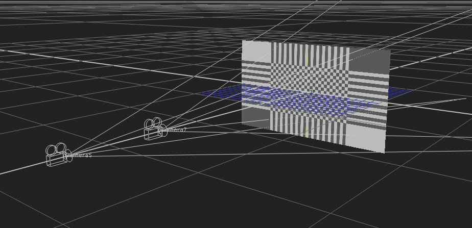 Right now, you can visualize the projection setup from the ScanlineRender node and you can see the checkerboard projected on the card.
 Note: Before you move forward, I would highly recommend you to take the time to check Camera node and Scanline render node parameters. Try to compare them with the similar menus from a 3D software. In production you will have to do this on daily basis while you compare if your Nuke Camera matches with what other departments are rendering (layout, anim, and lighting).
b. Building a projection layout:
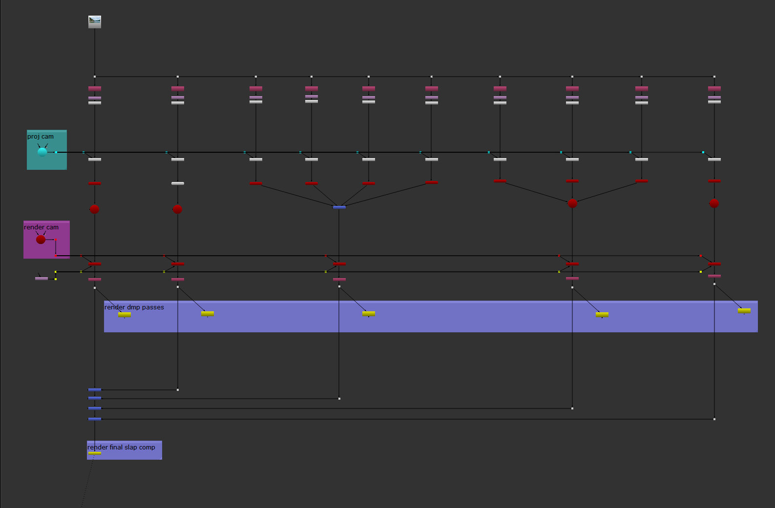
In the last part of this tutorial, I uploaded the layers that we painted in Photoshop in order to build a projection setup. This is how a projection should look like for a production workflow:
Note: for this part of the tutorial you will find the script with all the steps for creating a projection in the Nuke folder.
 First load the 2D file with multiple layers (could be PSD, TIF or preferably EXR) then create the following nodes:
1. Shuffle node – will isolate one dmp layer from your 2D file. Go to its settings parameters and from the in 1 value, select one pass at the time, like in my layout.
Note: you can create the shuffle nodes split automatically, by simply loading the PSD file and pressing the button Breakout Layers, from the PSD read node settings. This will create a layout with all the layers you saved from Photoshop. From that layout keep just the shuffle node and the read node. Then replace the PSD with the EXR source. EXR has 32bits/ channel compared with 16bits in the PSD file. In the houses with solid pipelines, you will export in EXR format, but in smaller studious you may use either Tiffs or PSD file export.
2. Reformat node – this will reformat the file to Full HD (remember we added Overscan). From the setting, under the resize type>none/ check center/ check preserve bounding box. It should look like the image bellow:
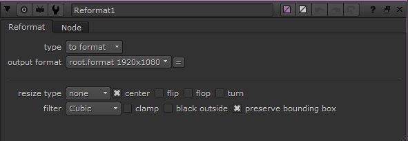 none parameter – it is cropping the center from the loaded image’s resolution, based on the values matched in the output format.
x preserve bounding box – does not remove the overscan after reformat, it’s kept accessible by the render camera, outside of the resolution size. It is not visible unless we move the render Camera or we have lens distortion.
3. Premult node – I will explain it in a larger context, into the next chapter. On short it is dividing the RGB information to the Alpha channel.
4. ScanlineRender node – under the ScanlineRender settings tab I changed just the antialiasing from none to high. This will give me smooth edges for the projection. Pay attention here to the overscan parameter. In the future this parameter will create overscan for your future matte paintings. For example, increase the value from 0 to 400.
For all the other nodes not mentioned from the projection setup, I left the parameters by default.
Projection Camera
For setting up the projection camera, simply take the render camera, duplicate it and remove the animation. In the current situation, I took the render camera at the frame 1001, because I have most of the visibility of the shot, then duplicate it and remove the animation.
Note: there are few options on how to decide to setup the camera for projection:
1. Choose the first, the last or an in-between frame of your shot, in which you see most of the area of your painting. Then in the ScanlineRender node, under the ScanlineRender tab’s settings, increase the overscan from 0 to something like 400px. This is what you will use in probably 70% of the cases in the daily production workflow. I will cover this solution in the last Chapter.
2. You can create multiple projection Cameras, to cover the movement of render Camera. Then you will merge the multiple projections with a MergeMat node. This will be like 25% of the situation in a daily production workflow.
3. You can create a custom camera for projection, totally off from the render Camera. This will be a very particular case and I personally have to use it for two or three times, during a year of work.
Note: The multiple projection Camera (point 2) and custom Camera (point 3) for projection are not covered during the course of this tutorial. I will probably create a different tutorial just for this, sins requires intermediate to advance knowledge in Nuke.
Note: When you build the layout for the projection, you have to split in multiple passes, based on personal judgement. This is to give flexibility for integration and adjustments to the compositing department. You will see separate writing nodes for water, sky, background, mid ground, and foreground elements.
For a clean understanding of your work, or if another artists needs to pick up your work, always organize your layout in a clean way, either on horizontal or vertical.This is where we end our first Chapter, we will continue with the next one: Linear workflow and color adjustments.
Note The exercise in this first chapter has the purpose to offer a general overview of the steps you need to follow to create a matte paint. The work itself is not solid enough to be used in a demoreel. You have to prove your ability to paint light, color, perspective integration. This is what we will do in Chapter III.![]()