
3. Advance matte paint creation – Part I
Summary – In this tutorial we will put together what we learned in the Chapter I and II. We will start by setting up the Camera Projection and then we will match textures with the 3D layout. In the end we will integrate the texture’s values and paint the light.
The first part of this tutorial will be focused on how to build our paint in Photoshop. For the second part, we will assemble everything in Nuke and render it for final delivery to comp.
Note: comp = compositing department.
I. Defining the 2.5D projection
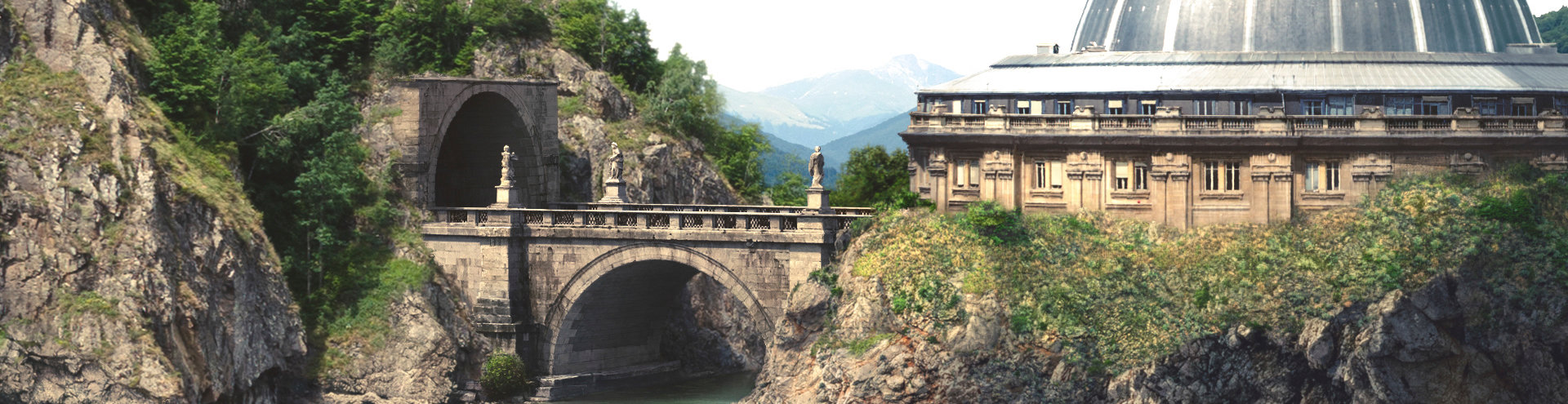
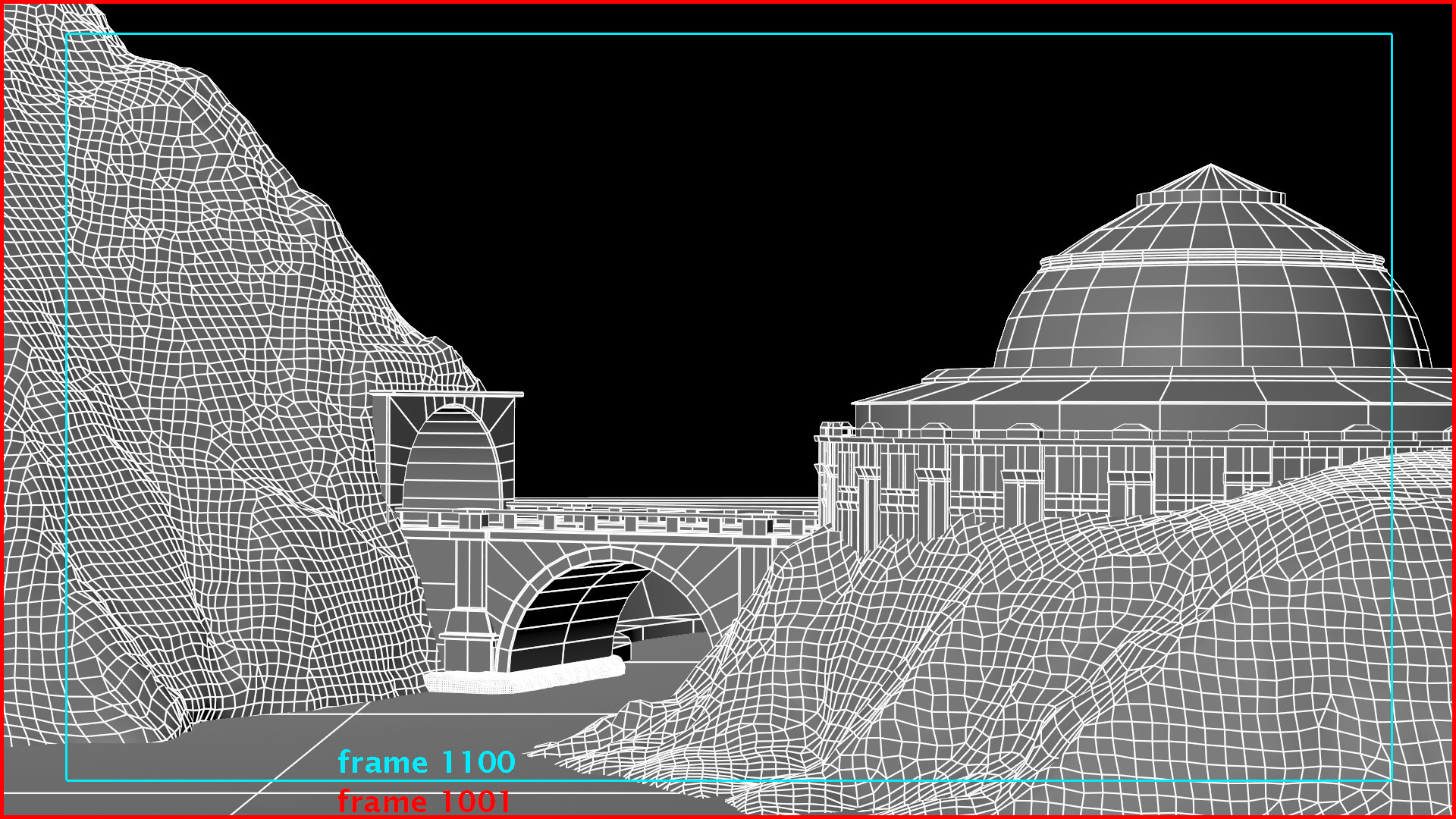
We have the 3D layout and the render camera approved, now the production assigns the texturing task of this environment to a matte paint artist (this is a contextual scenario). Based on our current render camera movement, first frame (fr1001) offers the widest angle of view. This is why we will use this frame to define the current projection. See the frames 1001 and 1100 bellow for comparison:
In order to start the camera projection set up, load the geo from the layout in either: OBJ, ABC or FBX format. I export it in ABC format for this tutorial.
Note: For loading geo from external sources create ReadGeo node, then under the file, load the geo you need.
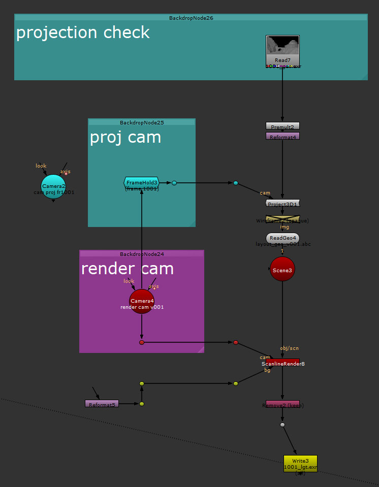
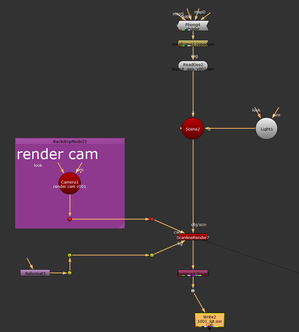 Build a projection rig with the geometry imported from the abc file. You can find the abc file under the OBJ folder (layout_geo_v001.abc). At this stage it is very hard to see the volume of the geo in Nuke, while we visualise it from the ScanlineRender node. To fix this I added a few extra nodes: a phong shader that I plug it above the readGeo node, a wireframe node to see the tessellation (toggle between disable or enable) and I connect a Light node to the Scene node. Lift the light above the scene in the 3D viewer (we discussed how to access and navigate in the 3D viewer in the first chapter) so we can see the volumes. If needed, increase the intensity of the light node. Your Nuke script should look like in the image on the side.
Note: Use the wireframe node just to create wireframes, but in order to see just the layout lit, you will have to disable it. To disable any node in Nuke, select the node and then press “d” on your keyboard. If you press “d” again, over a disabled node, you will enable it.
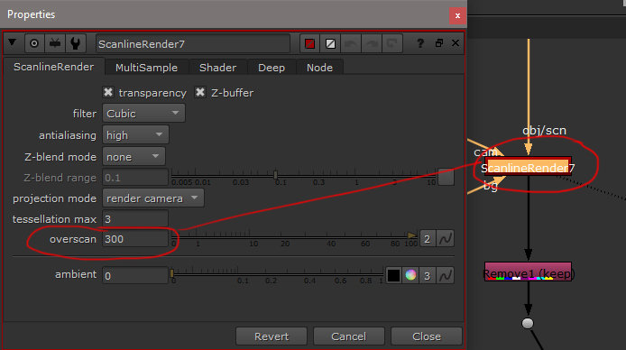 Once the rig is build and we can see the 3D scene, go to the ScanlineRender node and extend the Overscan from 0 to 300. See the image on the side.
Note: Based on each studio’s workflow, you may simply load the geo in Nuke and the render camera, straight from the pipeline, or you will have to export it to Nuke from a 3D package, used by your studio. The render camera should be provided to you, by the layout department, you don’t have to create it.
I personally recommend you to simplify the geo every time, from layout, in a 3D package and then export it to Nuke. You can import high amount of triangles but this will make Nuke very slow, compared with Maya or 3Ds Max. The current layout geo that I build is a light one; this is why it’s handled very well by Nuke.
Project’s Resolution
For this project we use Full HD resolution (1920×1080px). Set your nuke scene and your reformat node to Full HD.
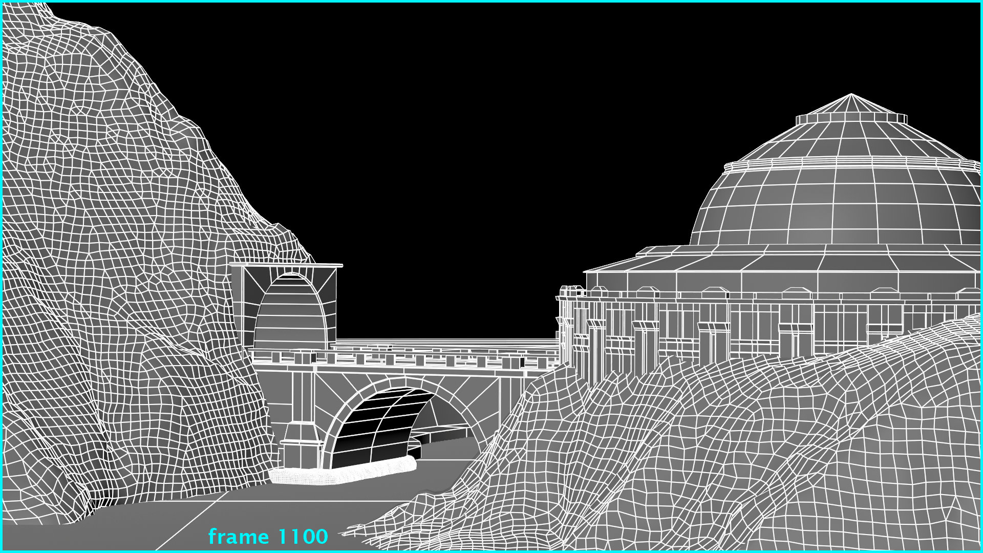
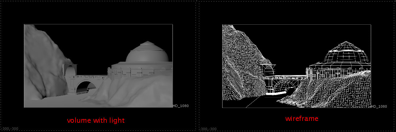
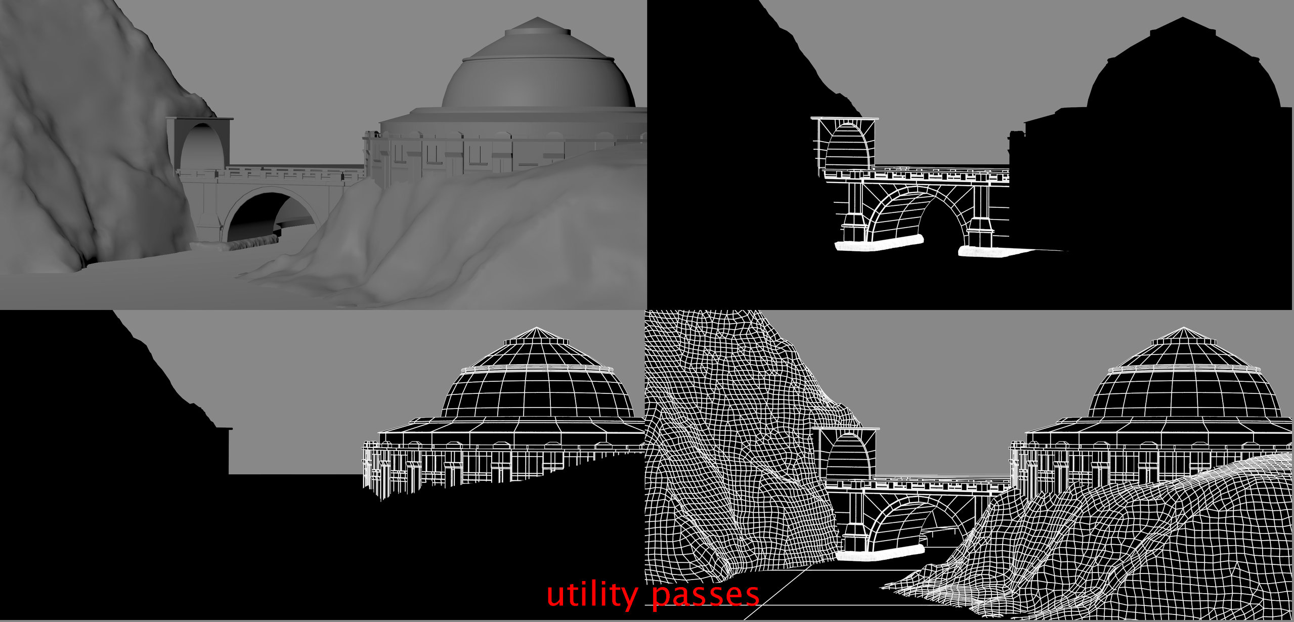
The final image rendered with volume and wireframes plus overscan 300 should look like the images bellow:
Camera Projection
So far, we have the rig for rendering the 3D layout on which we will match our matte paint. Next we have to check if our frame, that we want to use for projection, works with the shot.
Render the frame 1001 and then project it from the first frame over the geometry.
In the first chapter, concerning the projection camera, I mentioned that we have to duplicate the render camera and delete the animation. This time we’ll simplify the script with the following node:
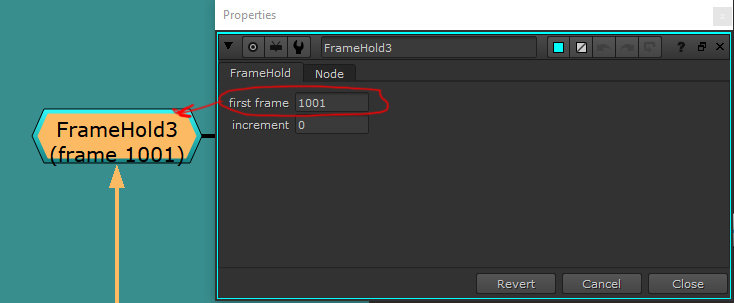 FrameHold node – in order to make the Nuke script lighter we’ll use this node to replace the projection camera. This node holds the animation, to a specific frame that we define under its parameters. For the current case it is frame 1001.
Connect the input of this node with the render camera and the output with the Project3D. The script should look like the one bellow:
Note: the frameHold node, by default will have a light yellow color, ignore the custom one create it here. If you want to customize the colors or borders of each node, check the two squares at the top of the node’s properties.
At the top of the script for projection, plug the rendered image (volume with light), premultiply it and then reformat it to Full HD.The premult is required to avoid any color bleeding from RGB channels, when we project it.
Finally, check the animation on the render camera to see how the projection covers the shot. For this particular shot we should be fine with just one frame for camera projection.
Utility Passes
Once the projection frame is defined for our matte paint you can render different utility passes.
Based on your needs, these utility passes will help you build the matte paint. For example you can render: mattes for different elements, wireframes, light pass, ambient occlusion or anything you consider will be useful for your matte painting.
The set of utility passes, I used for this tutorial, can be found under the PSD/render’s folder.
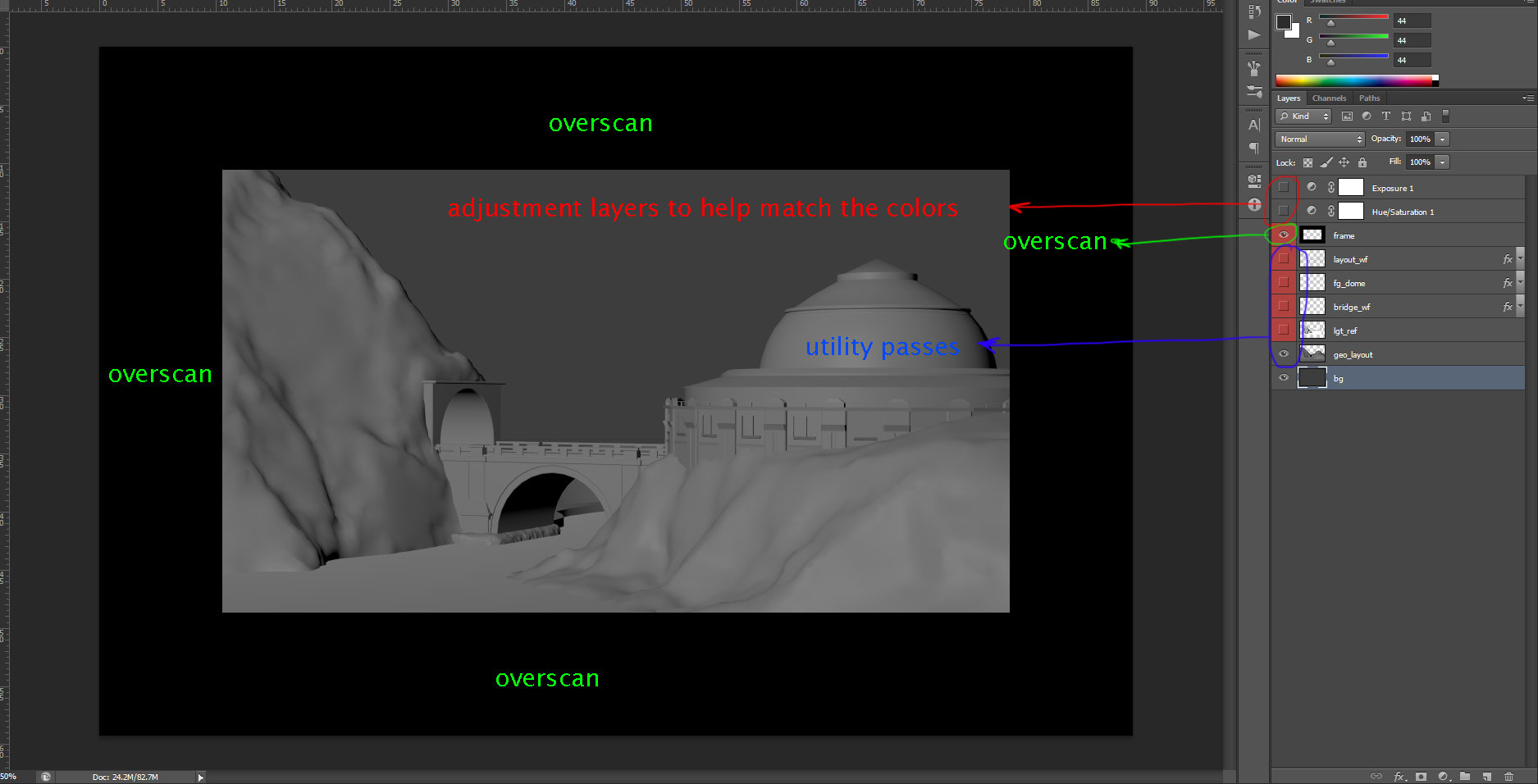
When we finish setting the projection in Nuke, we render everything in EXR format and we move to Photoshop. The EXR is the only format that will store the overscan. This will later on be revealed in Photoshop. For the write node, I left everything by default; just set the extension to EXR.
Once an image has an overscan defined in Nuke, you can see a dot line in the viewer, outside of the resolution’s box of an image.
II. Matching perspective in Photoshop based on 3D Layout
The preliminary layout in Photoshop, with the utility passes will look like this:
When an exr is loaded in Photoshop, even if it’s saved as a half float (16bits), it will be read as 32bits. Photoshop doesn’t understand the difference between float half (16 bits) and float full (32bits).
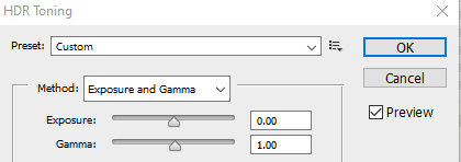 Once the image is loaded, go to Image>Mode and switch from 32bits to 16bits. A window will pop up and you will have to select either Merge or Don’t Merge. Following your selection, another window with HDR Toning will open. Here you will have different options on how to translate the 32bits depth to 16bits. I prefer to use Exposure and Gamma and let everything else by default, then press OK.
Note: In the companies with solid workflow, the conversions to 16bits in Photoshop, of the EXRs exported, will be done with a Photoshop Action, or automatically through the pipeline.
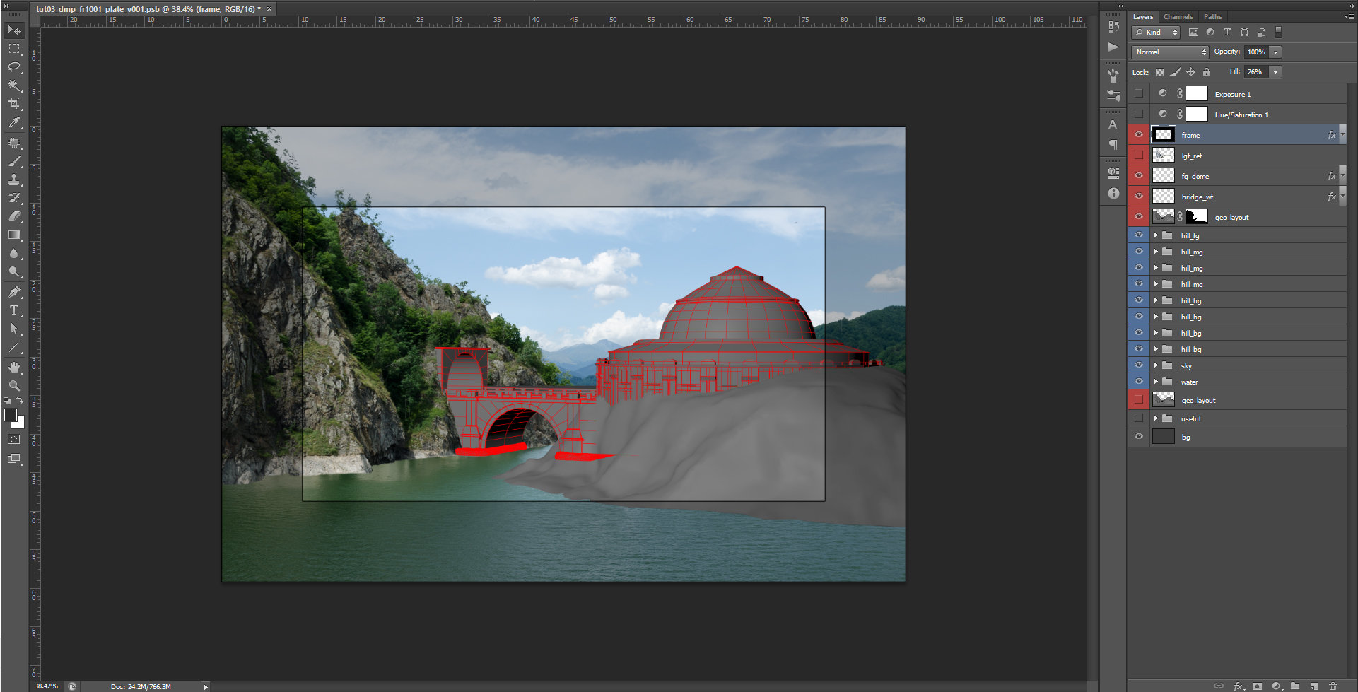
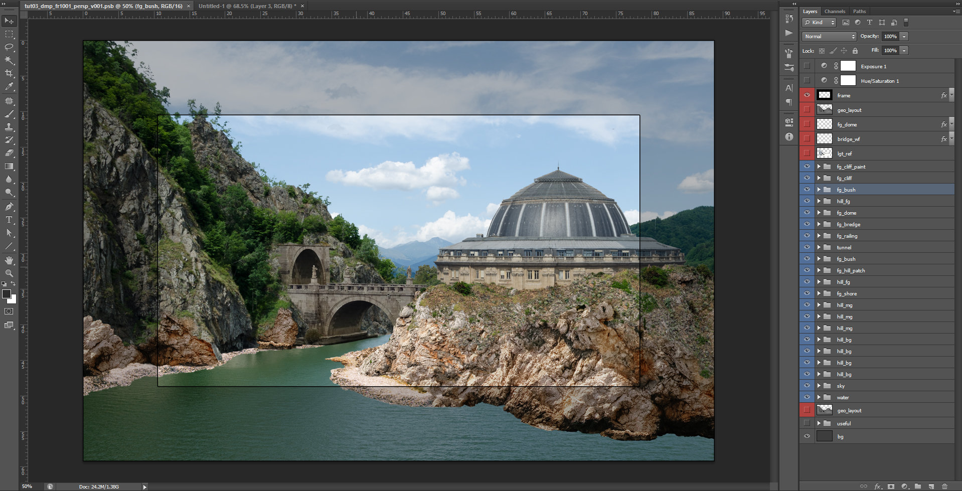
Your rendered layout is loaded in Photoshop; it is time to find images that will match the visual look of your future matte paint.For this scene, I reused the background from the first Chapter and I treated it like a plate (the base to follow for color integration, light and perspective). The scene looks like this:
In order to match the images from external sources with the plate’s perspective I used Free Transform (CTRL+t) and Puppet Warp. Puppet Warp can be found under the Edit tab. There are other methods too, so feel free to explore and define your own workflow.
Note: Personally, I prefer to convert the layers to smart objects (for backup up reasons). If a supervisor will ask you to scale up or down the painting; the resolution of the original images used, will be preserved. The downside of this process is that the PSB file gets heavier.
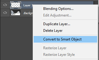 To convert a layer to a smart object, select the layer, press RMB and select from the menu Convert to Smart Object.
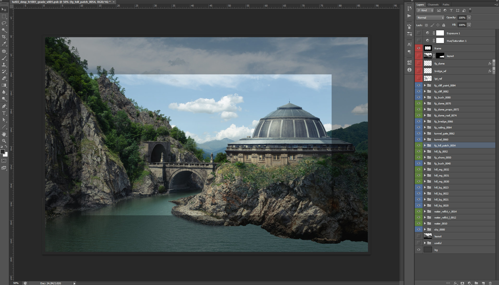
 For the current dmp project, you will find all the reference images used under the ref folder. Your paint, with the images lined up to match the current layout should look like this:
 At this stage, everything is split on multiple layers and there is no color and light integration yet. You can turn the wireframes on and off constantly to check the perspective. Some of the painted layers are not following entirely the volume of the layout. This is acceptable as long as they look correct.
 For continuity reasons of the rock patterns, I painted some areas on the left shore, with the same rock textures that I used on the right shore. Following, we will have to match the values with the plate and paint the light and shadow.
III. Color and light integration
All the steps used for doing an integration of a layer with the plate, were explained in Chapter II.
I will reiterate the steps you should always pay attention, before you start grading:
– perspective – match it with the layout.
Note: The easiest way to match the perspective of a dmp, is to simply render a 3D scene in Maya or 3Ds Max with the camera lens that is used by your shot. If you don’t have a layout, just place some basic volumes that represent your dmp composition, in a 3D software and render them.
– light on the plate is casted from back left side, at a very steep angle, like a mid-day sun position.– bright and dark values – use Hue/Saturation and Exposure layer in Photoshop, so you can determine the differences between the layer you add and the plate.
–color values – the images we add from external sources may have the dark/bright value tinted differently, or they may have a global color that is different from the plate context on which we want to integrate it.
– sharpen or blurriness of the original plate, have to be match too.
– refining – will be the extra layers of paint where you can add few extra bits that will give consistency to your painting. Here you can add any color adjustment or painting layers that you feel will give that extra refinement to you painting.
Light and shadow accuracy
To have an accurate direction of the light, I prepare a fast 3D scene and render it for light reference. You can see it bellow:
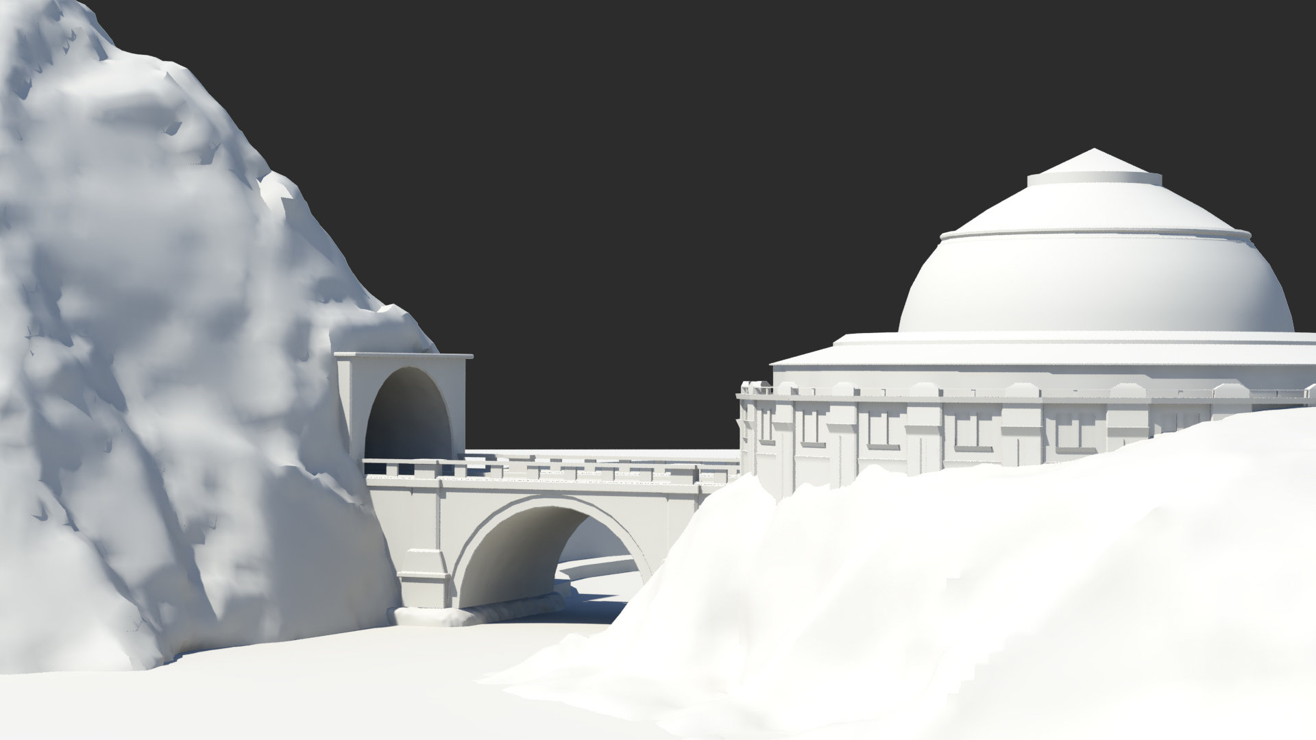
Note: In production, I recommend you to always render a scene with light casted over the volumes that you will paint. This is to avoid any later misinterpretation, from the supervisors, over how the light is painted in your scene.
Water Reflections
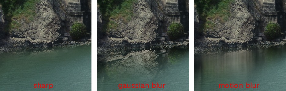 Select the paint from above the water, mirror it and then duplicate it three times. The first layer leave it the way it is, on the second one use a Gaussian blur filter and for the third one, use a Motion blur filter on vertical. In the end create a blending, by painting the masks of each layer.
Naturally a reflection, will have a bit of sharpness right on the edge that intersects with the reflected rock wall, then becomes Gaussian blur and further away becomes Motion blur, while is fading.
Final Matte Paint
Once the grading and light pass are finalized, for each matte paint layer, the final image will look like this:
Note: You can add more elements in the composition, or change the sky with one that has more drama. It doesn’t matter what direction you choose. The steps that need to be followed are the same I explained above: match the perspective and then match the color values and the light direction.
At the end of our painting, we will remove any unnecessary layers; we’ll collapse all the dmp groups and save either PSD or EXR, so we can use it in Nuke for building the parallax.